|
<< Click to Display Table of Contents >> RelatePosition Settings |
  
|
|
<< Click to Display Table of Contents >> RelatePosition Settings |
|
![]() The Positions Settings panel is used to specify options and limits that control the stacking operation.
The Positions Settings panel is used to specify options and limits that control the stacking operation.
Each assembly position has setting options tailored to the specific location in the structure.
Some settings are more general in nature and may be present for more than one position.
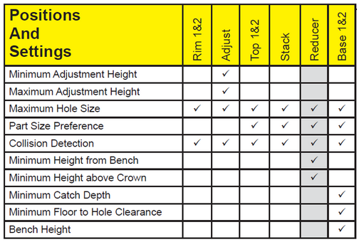
The chart above shows the positions across the top with a check mark where settings are appropriate.
Minimum Adjustment Height
This setting specifies the Minimum Adjustment Height to be included in the structure.
If the Minimum Adjustment Height is specified to be zero, the structure will be stacked with no adjustment pieces if possible.
Maximum Adjustment Height
This setting specifies the Maximum Adjustment Height allowable in the structure.
If the Maximum Adjustment Height is set to zero, there will be no limit on the maximum number of adjustment pieces used in the structure.
Typically additional adjustment parts are used up to the point that the next larger stack section is used, and the adjustment height is reduced accordingly.
Maximum Hole Size
The Maximum Hole Size specifies the largest hole size allowed in this position for a pipe penetration.
NOTE: Setting the Maximum Hole Size too small for some assembly positions (Base 1 & 2, Stack, and in some cases Top 1 & 2) can make it impossible to successfully stack structures.
Part Size Preference
The Part Size Preference option is used to indicate whether short or tall parts are preferred in the situation where all other considerations are equal.
Collision Detection
The Collision Detection option determines the action to be taken when a pipe enters this part position.
The four settings for this option are None, Seam, Severe,and Abort.
None
When the collision detection is set to None, no collision processing is performed for this part position.
Seam
When the collision detection is set to Seam, collisions between pipe cutouts and structure seams are minimized. A standard warning is displayed when collisions cannot be avoided.
Severe
When the collision detection is set to Severe, collisions between pipe cutouts and structure seams are minimized. A severe warning is displayed when collisions cannot be avoided.
Abort
When the collision detection is set to Abort, no pipe cutout collisions are allowed in this position. When it is not possible to stack the structure without placing the hole cutout in this position, the stacking process is aborted.
Minimum Height from Bench
The Minimum Height from Bench specifies the distance from the top of the bench (i.e. invert channel) to the underside of the reducing slab.
Minimum Height above Crown
The Minimum Height above Crown field specifies the distance from the crown of the highest hole cutout to the underside of the reducing slab.
If the Minimum Height above Crown is zero, then the reducing slab will always be at or above the crown of the highest pipe hole.
If a value greater than zero is entered, the reducing slab will always clear the highest pipe by the amount specified.
If the Minimum Height above Crown is left blank, the position of the reducing slab is determined by the Minimum Height from Bench dimension. This may allow pipes to enter the structure above the reducing slab.
Minimum Catch Depth
The Minimum Catch Depth specifies the distance from the lowest hole to the top of the floor.
The Minimum Catch Depth is specified from the flow line of the pipe, or from the bottom of the hole cutout.
|
More information |
Minimum Floor to Hole Clearance
The Minimum Floor to Hole Clearance specifies the distance from the bottom of the lowest hole cutout to the top of the floor.
The Minimum Floor to Hole Clearance and the Minimum Catch Depth work together to determine position of the floor.
Bench Height
The bench height field specifies the height of the bench (i.e. top of invert channel) relative to the diameter of the invert pipe.
The options for this field are 0%, 25%, 50%, 75%, and 100%.