|
<< Click to Display Table of Contents >> Quote - Detail BuildDimensions |
  
|
|
<< Click to Display Table of Contents >> Quote - Detail BuildDimensions |
|
![]() The Dimensions panel is used to enter the elevation, angle, pipe and connector specifications for the structure.
The Dimensions panel is used to enter the elevation, angle, pipe and connector specifications for the structure.
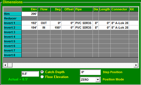
Dimension Data
The data fields control the placement of the Rim, Reducer, and Inverts (outlet and inlets) in the assembly.
Click anywhere on a row in the Dimensions panel to activate the data fields for that row.
NOTE: Double click on the row name to clear the row.
The width of the columns are adjusted by holding down the left mouse button on the dividing line between the column headers and dragging the column divider to the desired column width.
To access a menu for configuring the data grid, click the right mouse button on the green header row. The menu provides options to add or remove columns, and to resize the columns to fit the data they contain.
Elevations
Enter the required elevations in the edit field for the active row. The elevations are measured at the upper surface for the Rim, at the lower surface for the Reducer, and at the flow line of the pipe for the Inverts (outlet and inlets).
When the Elevation field is selected, pressing the plus or minus key on the keyboard will increase or decrease the current elevation by 0.1 foot.
For Inverts, the % of Grade may also be entered. To include the % of Grade, enter the elevation followed by the "at" sign (@) and the number for the % of Grade (i.e. 120@5 means the elevation is 120 with a 5% slope up going away from the structure, 254.55@-7 means the elevation is 254.55 with a slope of 7% going down from the structure.)
Flow
Specify the flow direction by choosing one of the options for this field. For inverts flowing into the structure select “IN.” For outward flow select “OUT.”
Degrees
The Angle is measured in degrees from zero to the Invert center-line. Pull down the list and select the desired angle. Angles other than those listed may be typed into the field.
Hole Offset
The Offset provides the ability to adjust the invert location by applying an offset perpendicular to the radial line. This enables creating and displaying structures with pipes that are not aligned with the center of the structure, such as pump stations.
The Offset dimension unit of measure is configured on the Unit of Measure Setup panel in the User Setup Options screen.
Pipe Type
Pipe definitions are established on the Stock screen. Pull down the Pipe list and select the desired pipe type. If a new pipe definition is needed it must be added to the Stock screen by the administrator.
Pipe Diameter
The Diameter is the inside diameter of the pipe. Pull down the Diameter list and select the desired pipe diameter. Pipe diameters are part of the pipe definitions established on the Stock screen.
Pipe Length
The Length provides the ability to account for the number of pipe lengths that will be required to accomplish the pipe run.
STACK-IT will divide the length of the pipe run by the length of an uncut section of the specified pipe (as configured on the Stock screen). Any fractional values will be rounded up to the next full length of pipe. For example, a pipe run that requires 7.75 lengths of pipe will show as 8 lengths of pipe in the list of materials for the structure.
Connector
Connectors are established on the Stock screen. Pull down the Connector list and select the desired connector. If a different connector definition is needed it must be added to the Stock screen by the administrator.
If Connector Preferences are enabled this list will show only the preferred connectors for the selected pipe, and an option to override the connector preferences.
Connector Kits
Connector Kits are a convenient way to add ancillary connector parts. To add a Connector Kit to the currently selected invert, click the Kit button to open the Connector Kit Selector screen.
|
More information |
Catch Depth / Floor Elevation
![]() The Catch Depth / Floor Elevation field controls the location of the structure floor. When "Catch Depth" is selected, the floor will be positioned at the specified distance below the lowest invert.
The Catch Depth / Floor Elevation field controls the location of the structure floor. When "Catch Depth" is selected, the floor will be positioned at the specified distance below the lowest invert.
The Catch Depth will default to the depth associated with the Base1 assembly position on the Relate screen.
When the catch depth specified requires moving the pipes up to parts above the base, STACK-IT will move the pipes automatically. When the “Floor Elevation” is selected, the floor will be positioned at the elevation specified.
Step Position
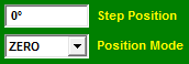 The Step Position field specifies the radial position of the steps on the structure wall.
The Position Mode setting determines the method calculating the Step Position. The settings are Auto, Manual, Outlet, Zero and Designer.
The Position Mode will default to the settings in the Relate - General Options screen.
Auto
The Step Position will automatically set to the largest degree space that is available. Example: For a structure with one Invert at 45 degrees and another at 135 degrees, the steps will be positioned at 270 degrees.
Manual
The Step Position must be entered manually. Entering a Step Position manually will change the Position Mode to Manual.
Outlet
The Step Position will be set to the same degree location as the Outlet.
Zero
The Step Position will be set to Zero degrees.
Designer
When the Top Opening Designer has been enabled, the Position Mode list will display the “Designer” setting. Changing the Position Mode to any other setting will disable the Top Opening Designer for the current structure.