|
<< Click to Display Table of Contents >> User Setup OptionsReport Mode Configuration |
  
|
|
<< Click to Display Table of Contents >> User Setup OptionsReport Mode Configuration |
|
This screen configures the modes that can be used to represent hole locations in printouts and on-screen drawings. For example, a cored part may have the hole location measured from the bottom of the part, while a cast part has the hole location measured from the top of the floor.
These modes are used on the Relate, Quote, and Quote Print screens, and will change the drawing characteristics to match the profile.
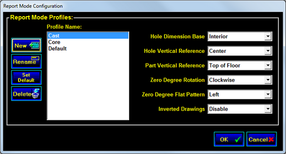
Hole Dimension Base
The Dimension Base specifies the basis on which the horizontal (around the structure) hole locations are measured (inside wall, outside wall or steel dimension.) These selections apply only to pages that display a Top View, Flat Pattern, or a data grid that includes the horizontal hole location.
If the Inside Wall or the Outside Wall is selected for printing, the corresponding line will be shown as a bold line in the top view.
If the Wire Dimension is selected for printing, a dashed line will be added to the top view.
Hole Vertical Reference
The Hole Vertical Reference specifies the hole position for the Up hole location dimension. The options are Top of hole, Center of hole, and Bottom of hole.
Part Vertical Reference
The Part Vertical Reference selects the part of the floor that will be used in calculating the Up hole location dimension. The options are Bottom of Part, Top of Floor, and Top of Part.
Zero Degree Rotation
The Zero Degree Rotation setting selects the direction in which STACK-IT should measure when doing circumferential or angular measurement. The available options are Clockwise and Counter-Clockwise.
Zero Degree Flat Pattern
Determines the side of the flat pattern that will represent the zero degree position. The available options are Left and Right.
Inverted Drawings
This setting enables drawing parts from an upside down perspective in page layout objects that have Inverted Drawing activated. The part being displayed must also have Inverted Drawing enabled in the MfgFlags specification field.
Command Buttons
![]() New
New
Click the New button to create a new report profile. STACK-IT will prompt you for a name for the new profile. If a profile was selected before the button was pushed, the old settings will be duplicated into the new profile.
![]() Rename
Rename
The Rename button is used to change a profile's name. STACK-IT will prompt you for the new name to give to the layout, and then will make the change.
![]() Set Default
Set Default
Pick the Set Default button to set the default settings to be the same as the currently selected profile. This will overwrite the settings that already exist in the default profile.
![]() Delete
Delete
The Delete button will erase the currently selected profile. You will be prompted to confirm your intent to delete before the profile is actually erased.
![]() OK
OK
Click the OK button to return to the Setup screen, and to keep the current mode profile settings. Any changes that were made since entering this screen will be saved.
![]() Cancel
Cancel
Select the Cancel button to return to the Setup screen, but to reject any changes that have been made since entering the Report Mode Configuration screen.